
이해가 되지 않는 부분은 아래의 코드처럼 카메라 생성 시 초기화로 카메라를 y축으로 180도 회전시켰는가… 이다.
cameraOrtho.rotation.y = Math.PI;
cameraPerspective.rotation.y = Math.PI;
이 글의 예제 코드는 THREE.JS 공식 사이트의 EXAMPLES에서 제공되는 코드를 이해하고 제 나름대로의 코드로 재구성한 것입니다.

공간정보시스템 / 3차원 시각화 / 딥러닝 기반 기술 연구소 @지오서비스(GEOSERVICE)
이해가 되지 않는 부분은 아래의 코드처럼 카메라 생성 시 초기화로 카메라를 y축으로 180도 회전시켰는가… 이다.
cameraOrtho.rotation.y = Math.PI; cameraPerspective.rotation.y = Math.PI;
이 글의 예제 코드는 THREE.JS 공식 사이트의 EXAMPLES에서 제공되는 코드를 이해하고 제 나름대로의 코드로 재구성한 것입니다.
_initialize 함수를 보면 아래의 변수가 정의되는 것을 볼 수 있습니다.
this._splineHelperObjects = [];
this._positions = [];
this._splines = {};
_splineHelperObjects는 스플라인의 제어점에 대한 Mesh 객체를 담고 있습니다. _positions는 _splineHelperObjects에 저장된 Mesh들의 position 속성 객체들 항목으로 참조하고 있고 _splines은 key-value 컨테이너로 uniform, centripetal, chordal를 key로 하여 THREE.CatmullRomCurve3 객체를 value로 가집니다. 이때 이 value에 mesh를 속성으로하여 THREE.Line 객체를 갖습니다.
이 글의 예제 코드는 THREE.JS 공식 사이트의 EXAMPLES에서 제공되는 코드를 이해하고 제 나름대로의 코드로 재구성한 것입니다.
3차원에서는 다양한 3차원 객체가 Scene Graph 형태로 구성되어 있습니다. 렌더링하는 결과에 따라 그 형태가 매우 복잡하게 구성될 수 있는데.. Scene Graph의 구성 요소를 확인하기 위한 간단한 함수입니다.
dumpVec3(v3, precision = 3) {
    return `${v3.x.toFixed(precision)}, ${v3.y.toFixed(precision)}, ${v3.z.toFixed(precision)}`;
}

dumpObject(obj, lines = [], isLast = true, prefix = '') {
    const localPrefix = isLast ? '└─' : '├─';
    lines.push(`${prefix}${prefix ? localPrefix : ''}${obj.name || '*no-name*'} [${obj.type}]`);
    const dataPrefix = obj.children.length
        ? (isLast ? '  │ ' : '│ │ ')
        : (isLast ? '    ' : '│   ');
    lines.push(`${prefix}${dataPrefix} pos: ${this.dumpVec3(obj.position)}`);
    lines.push(`${prefix}${dataPrefix} rot: ${this.dumpVec3(obj.rotation)}`);
    lines.push(`${prefix}${dataPrefix} scl: ${this.dumpVec3(obj.scale)}`);
    const newPrefix = prefix + (isLast ? '  ' : '│ ');
    const lastNdx = obj.children.length - 1;
    obj.children.forEach((child, ndx) => {
        const isLast = ndx === lastNdx;
        this.dumpObject(child, lines, isLast, newPrefix);
    });
    return lines;
}
사용은 다음과 같습니다.
console.log(this.dumpObject(root).join('\n'));
결과 예는 다음과 같습니다.
*no-name* [Scene]
  │  pos: 0.000, 0.000, 0.000
  │  rot: 0.000, 0.000, 0.000
  │  scl: 1.000, 1.000, 1.000
  ├─*no-name* [DirectionalLight]
  │    pos: -250.000, 800.000, -850.000
  │    rot: 0.000, 0.000, 0.000
  │    scl: 1.000, 1.000, 1.000
  ├─*no-name* [Object3D]
  │    pos: -550.000, 40.000, -450.000
  │    rot: 0.000, 0.000, 0.000
  │    scl: 1.000, 1.000, 1.000

...

  ├─*no-name* [Object3D]
  │ │  pos: 571.897, -76.040, -1163.608
  │ │  rot: 0.000, 0.000, 0.000
  │ │  scl: 1.000, 1.000, 1.000
  │ └─CAR_03_3 [Object3D]
  │   │  pos: 0.000, 33.000, 0.000
  │   │  rot: 0.000, 3.142, 0.000
  │   │  scl: 1.500, 1.500, 1.500
  │   └─CAR_03_3_World_ap_0 [Mesh]
  │        pos: 0.000, 0.000, 0.000
  │        rot: 0.000, 0.000, 0.000
  │        scl: 1.000, 1.000, 1.000
  └─*no-name* [Line]
       pos: 0.000, -621.000, 0.000
       rot: 0.000, 0.000, 0.000
       scl: 100.000, 100.000, 100.000
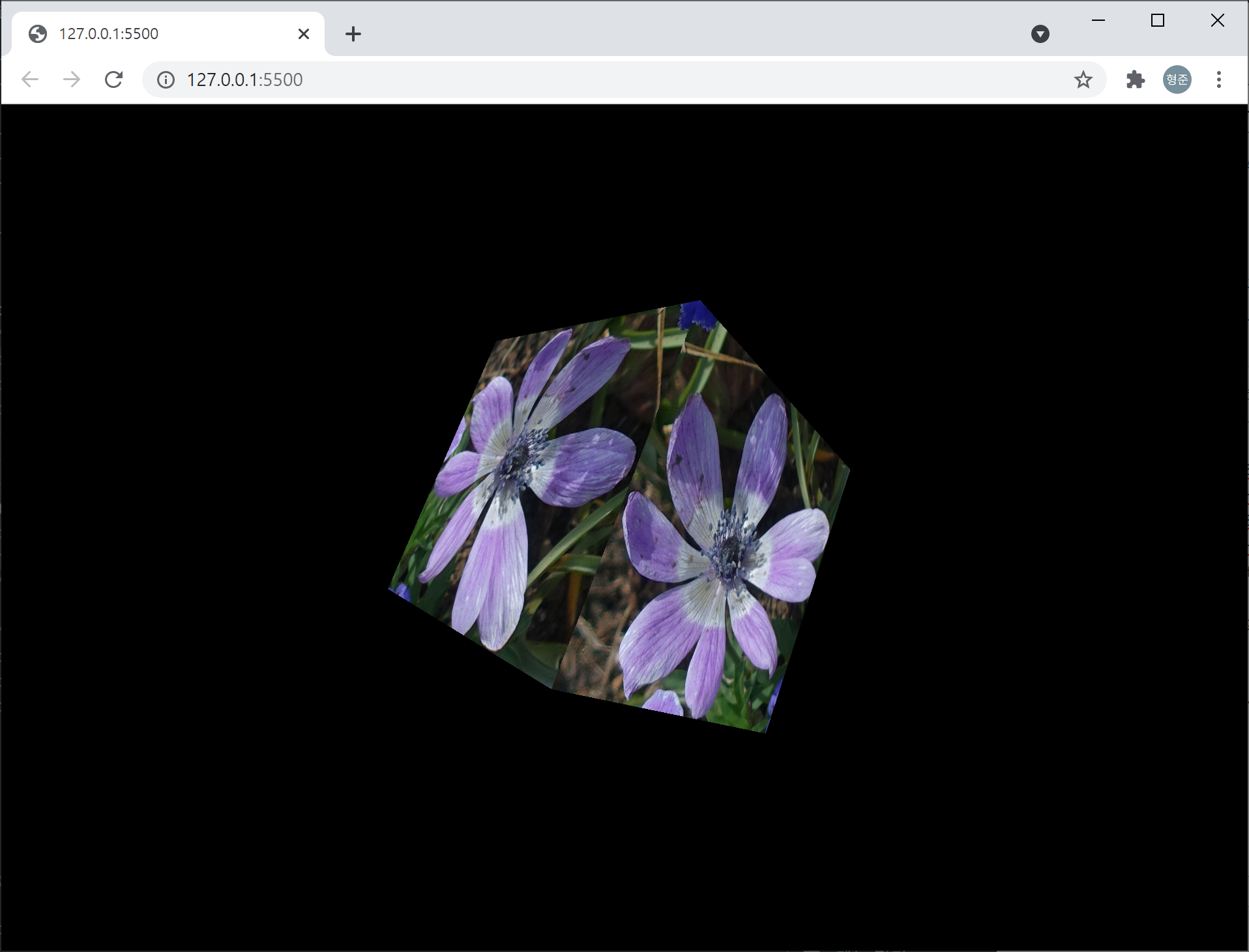
three.js에서 제공하는 기본 정육면체에 대해 텍스쳐 맵핑을 하는 코드는 다음과 같습니다.
const geometry = new THREE.BoxGeometry(1, 1, 1);
const loader = new THREE.TextureLoader();
const material = new THREE.MeshBasicMaterial({
    map: loader.load("flower-5.jpg", undefined, undefined, function(err) {
        alert('Error');
    }),
});
const cube = new THREE.Mesh(geometry, material);
this.scene.add(cube);
실행하면 다음과 같은 결과를 얻을 수 있습니다.
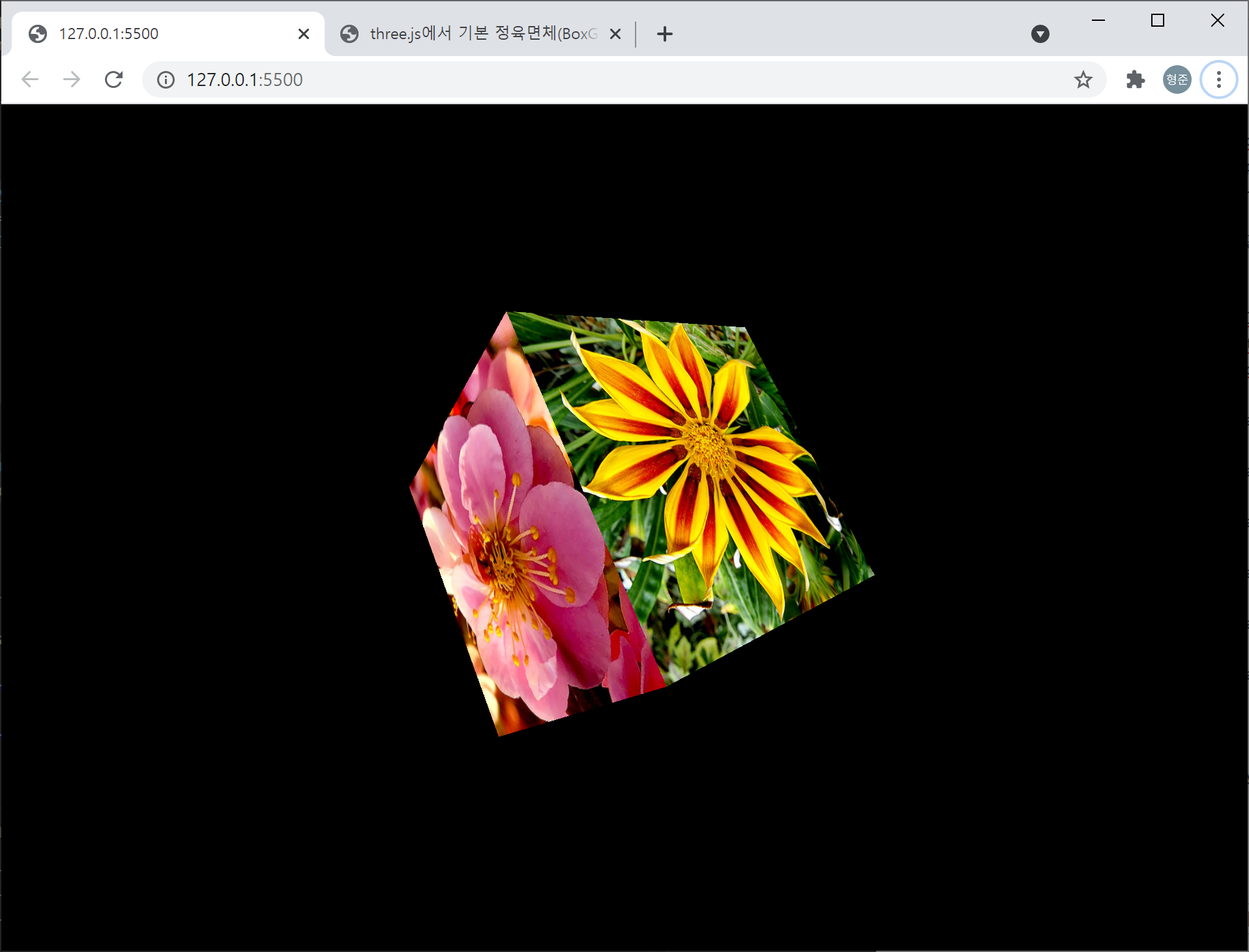
그런데 이 THREE.BoxGeometry는 각 면에 대해 다른 텍스쳐 맵핑을 지정할 수 있습니다. 아래처럼요.
const geometry = new THREE.BoxGeometry(1, 1, 1);
const loader = new THREE.TextureLoader();
const materials = [
    new THREE.MeshBasicMaterial({ map: loader.load("flower-1.jpg") }),
    new THREE.MeshBasicMaterial({ map: loader.load("flower-2.jpg") }),
    new THREE.MeshBasicMaterial({ map: loader.load("flower-3.jpg") }),
    new THREE.MeshBasicMaterial({ map: loader.load("flower-4.jpg") }),
    new THREE.MeshBasicMaterial({ map: loader.load("flower-5.jpg") }),
    new THREE.MeshBasicMaterial({ map: loader.load("flower-6.jpg") }),
];

const cube = new THREE.Mesh(geometry, materials);
this.scene.add(cube);
결과는 다음과 같습니다.
이 글은 three.js의 전체 코드가 아닌 정육면체에 텍스쳐 맵핑에 대한 코드만을 언급하고 있습니다. 전체 코드에 대한 뼈대는 아래 글을 참고 하시기 바랍니다. 위의 코드들은 모두 _setupModel 함수의 코드입니다.
구현하고자 하는 결과는 아래의 그림처럼 노란색 경로가 있고 빨간색 직육면체가 이 경로를 따라 자연스럽게 이동하는 것입니다.
먼저 제가 사용하는 three.js의 구성 중 거의 변경되지 않는 HTML과 CSS를 살펴보겠습니다. HTML은 다음과 같습니다.
<!DOCTYPE html>
<html>
    <head>
        <meta name="viewport" content="width=device-width, initial-scale=1">
        <link rel="stylesheet" href="style.css">
        <script type="module" src="app.js" defer>
    </head>
    <body>
    </body>
</html>
CSS는 다음과 같구요.
* {
    outline: none;
    padding: 0;
    margin: 0;
}
그리고 이제 app.js에 대한 코드를 살펴보겠습니다. 먼저 기초 코드입니다.
import * as THREE from 'https://cdnjs.cloudflare.com/ajax/libs/three.js/r126/three.module.min.js'

class App {
    constructor() {
        this._initialize();
    }

    _initialize() {
        this.domWebGL = document.createElement('div');
        document.body.appendChild(this.domWebGL);

        let scene = new THREE.Scene();
        let renderer = new THREE.WebGLRenderer();

        renderer.setClearColor(0x000000, 1.0);
        this.domWebGL.appendChild(renderer.domElement);
        window.onresize = this.resize.bind(this);

        this.renderer = renderer;
        this.scene = scene;

        this._setupModel();
        this._setupLights()
        this._setupCamera();

        this.resize();
    }

    _setupModel() {
        // 경로 및 직사각형 모델 구성
    }

    update(time) {
        // 직사각형 모델을 경로에 따라 이동시킴
    }

    _setupLights() {
        const light = new THREE.DirectionalLight(0xffffff, 1);
        light.position.set(30, 50, 20);
        this.scene.add(light);
    }

    _setupCamera() {
        const fov = 60;
        const aspect = 1;
        const zNear = 0.1;
        const zFar = 1000;

        let camera = new THREE.PerspectiveCamera(fov, aspect, zNear, zFar);

        camera.position.set(40, 40, 40).multiplyScalar(0.3);
        camera.lookAt(0,-2,0);

        this.scene.add(camera);
        this.camera = camera;
    }

    render(time) {
        requestAnimationFrame(this.render.bind(this));

        this.update(time);
        this.renderer.render(this.scene, this.camera);
    }

    resize() {
        let camera = this.camera;
        let renderer = this.renderer;

        renderer.setPixelRatio(window.devicePixelRatio);
        renderer.setSize(window.innerWidth, window.innerHeight);

        camera.aspect = window.innerWidth / window.innerHeight;
        camera.updateProjectionMatrix();
    }
}

window.onload = function() {
    (new App()).render(0);
}
위의 코드에서 경로와 정육면체 매쉬를 구성하는 _setupModel과 매쉬 모델을 움직이도록 속성값을 업데이트하는 update 함수는 아직 비어 있습니다.
모델을 구성하는 _setupModel 함수의 코드는 다음과 같습니다.
_setupModel() {
    const path = new THREE.SplineCurve( [
        new THREE.Vector2( 10, 5 ),
        new THREE.Vector2( 5, 5 ),
        new THREE.Vector2( 5, 10 ),
        new THREE.Vector2( -5, 10 ),
        new THREE.Vector2( -5, 5 ),
        new THREE.Vector2( -10, 5 ),
        new THREE.Vector2( -10, -5 ),
        new THREE.Vector2( -5, -5 ),
        new THREE.Vector2( -5, -10 ),
        new THREE.Vector2( 5, -10 ),
        new THREE.Vector2( 5, -5 ),
        new THREE.Vector2( 10, -5 ),
        new THREE.Vector2( 10, 5 ),
    ] );

    this.path = path;

    const points = path.getPoints( 100 );
    const geometry = new THREE.BufferGeometry().setFromPoints( points );
    const material = new THREE.LineBasicMaterial( { color : 0xffff00 } );
    const pathLine = new THREE.Line( geometry, material );
    pathLine.rotation.x = Math.PI * .5;
    this.scene.add(pathLine);

    const boxGeometry = new THREE.BoxGeometry(1, 1, 3);
    const boxMaterial = new THREE.MeshPhongMaterial({color: 0xff0000});
    const boxMesh = new THREE.Mesh(boxGeometry, boxMaterial);
    this.scene.add(boxMesh);

    this.boxMesh = boxMesh;
}
그리고 update 함수는 다음과 같습니다.
update(time) {
    const boxTime = time * .0001;

    const boxPosition = new THREE.Vector3();
    const boxNextPosition = new THREE.Vector2();

    this.path.getPointAt(boxTime % 1, boxPosition);
    this.path.getPointAt((boxTime + 0.01) % 1, boxNextPosition);

    this.boxMesh.position.set(boxPosition.x, 0, boxPosition.y);
    this.boxMesh.lookAt(boxNextPosition.x, 0, boxNextPosition.y);
}
위의 코드 중 7과 8번 라인의 getPointAt은 경로를 구성하는 좌표를 얻을 수 있는데, 이 함수의 첫번째 인자는 0에서 1사이의 값을 가질 수 있고 0일때 경로의 시작점 1일때 경로의 끝점을 얻을 수 있습니다.